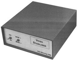
It was at this point that I became involved. The television manufacturer's UK agent was aware of the problem, but could not offer a modification to resolve it! I did not feel inclined to delve into the innards of the television without information, and my friend didn't really want to buy another set. The only remaining option was to design a device to remove the copy-protection from the signal before it reached the TV. The result is the Video Stabiliser described here.
Copy Protection
 The principle
of copy protection is to alter the video signal such that it can be displayed
normally on a TV or monitor, but not recorded by a video recorder.
By examining the signal with an oscilloscope, I found two areas where
it is altered.
The principle
of copy protection is to alter the video signal such that it can be displayed
normally on a TV or monitor, but not recorded by a video recorder.
By examining the signal with an oscilloscope, I found two areas where
it is altered.Firstly the video level in the top section of the picture, normally reserved for teletext information, is varied from black to peak white. Many video recorders use this part of the signal to set their automatic recording level, resulting in a signal with wildly varying amplitude that a television cannot successfully display.
Secondly the colour burst has a DC offset in the last few lines of the picture. This is visible on some televisions as a dark section at the bottom of the screen. Many video recorders will confuse this with the frame sync signal, and lock onto it instead of the true frame sync.
The Video Stabiliser presented here will remove both of the above signal alterations. The prototype enabled the author's friend to enjoy his new toy! Removal of the colour burst offset is optional and selected by a front panel switch. A second switch enables the unit to be bypassed when not required.
The prototype unit was connected between the video output connector on the video recorder and the video input connector on the television. If it is being used with a television that does not have a composite video input socket, the signal must be modulated before being fed to the aerial socket. This can be achieved by connecting the unit between two video recorders.
How It Works
The video enters the unit via PL1. SW1 selects whether the circuit is enabled or bypassed. R8 terminates the input.
The circuit around TR1 is a sync separator, the output across R4 pulses between 0V and 6V approx.
 TR2 is fed by an integrator
circuit to produce the frame sync. D5, R13 and C9 extend this over
the teletext area at the top of the screen. This is squared up by
the logic gate to form the Blank Enable signal, which is high during this
part of the picture.
TR2 is fed by an integrator
circuit to produce the frame sync. D5, R13 and C9 extend this over
the teletext area at the top of the screen. This is squared up by
the logic gate to form the Blank Enable signal, which is high during this
part of the picture.If SW2 is closed, D6, C10 and R14 extend the line sync pulse over the colour burst. The non-extended sync is gated with this to produce the Burst Enable signal, which is high during the colour burst.
Video Enable is high whenever the other two enable lines are low, and covers the normal video and sync part of the picture.
The Sync signal is inverted by IC1 and R6. This is then attenuated and set to a suitable DC level by R7, R9, R12, R13 and C5, and forms the blanked video signal.
The video signal is held with its base line at around 0V by C7, R10, and D2. This is the normal video. Note that D2 must be a germanium device.
C6, R16 and R17 remove all DC from the video signal and leave the chrominance and colour burst, biased a little above the 0V rail. This forms the chrominance signal.
These three signals are fed into analogue switches controlled by the enable lines. Only one switch is closed at a time, and consequently the required signal is assembled. The result is buffered by the output amplifier (TR3, TR4 and surrounding components). C13 adds a little HF boost to compensate for losses earlier in the circuit.
A supply of 9V (+/- 1V) at 35mA is required, this does not need to be regulated since the current consumption is reasonably constant. A low cost unit built into a large 13 Amp plug may be suitable - select one that can be left on indefinitely. If the voltage is selectable it may have to be set to 6V since the load is light.
Any ripple on the power supply output is removed by C12. D5 protects the unit against reverse polarity. The supply to the sync separator is further decoupled by R19 and C9.
Note that IC1 and IC2 are operated from a supply of about 6V (due to R14, R24 and C14). This is because the sync separator output only goes up to about 6V and a gate powered from the 9V rail would not respond to it.
Construction
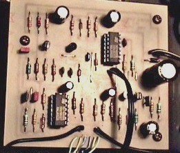
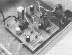 The circuit is constructed
on a single sided PCB, 84mm x 92mm. Construction is reasonably straightforward.
Start with the six wire links, and then continue in the usual size order.
IC1 and IC2 are both CMOS devices and IC sockets are recommended.
D2 is a germanium diode, take care to ensure that it does not get too
hot. Veropins or 0.1" header strip are recommended for the off-board
connection.
The circuit is constructed
on a single sided PCB, 84mm x 92mm. Construction is reasonably straightforward.
Start with the six wire links, and then continue in the usual size order.
IC1 and IC2 are both CMOS devices and IC sockets are recommended.
D2 is a germanium diode, take care to ensure that it does not get too
hot. Veropins or 0.1" header strip are recommended for the off-board
connection.Any case that is large enough to hold the PCB, sockets and switches would be suitable. A metal case may be preferable for screening but no problems were experiences with the prototype in its plastic box.
Screened cable may be used for the video connections, but this is not really necessary providing the wire is short.
The two switches can be considered as optional - if one or both are not required link wires should be fitted in the PCB as required.
Testing
Providing the unit is carefully constructed there is no reason why it shouldn't work first time. If an oscilloscope is available, the output can be viewed when playing a copy-protected tape to verify that the offending signals have been removed. Otherwise simply connect the unit to your equipment and try it!
Measure the voltage across C12, which must be 9V +/-1V. If the voltage is selectable on the PSU, try other settings to bring the voltage within range.
Alternatively, if the voltage is a little too high it may be possible to reduce it by connecting one or more 1N4001 diodes in series, in the positive connection to the PCB. Each diode will drop about 0.6V.
In some cases a dark section may be visible at the top of the screen. This is caused by the delay produced by R15 and C8 being longer than required. It appears that this delay differs slightly with different makes of 4001 IC, however the colour burst delay due to C10 and R18 is unaffected.
If this problem occurs there are two options. If you have a stock of IC's try some other 4001's to find one that's suitable. Otherwise try reducing the value of R15 to 27K or 22K, find the highest value where the dark section is not visible.
In Use
For normal viewing it may be preferable to set SW1 to bypass, to eliminate the inevitable slight signal degrading that this unit causes. When viewing a troublesome video film, the unit should be switched in. SW2 should only be closed if it proves necessary, since this may cause slight colour variation problems.
Please do not use this unit for any other purpose!
Parts List
Resistors (All 0.25W 5% or better)
R1,2 27K
R3,18 18K
R4 5K6
R5 22K
R6,9,11 4K7
R7 39K
R8,23 82R
R10 100K
R12 270K
R13 10K
R14 470R
R15,16 33K
R17,20,24 1K0
R19 270R
R21,25 100R
R22 2K2
Capacitors
C1,7 220n
C2,13 100u
C3,4 10n
C5 10u
C6, 11 220p
C8 100n
C9 220u
C10 470p
C12 2200u
C14 47u
Semiconductors
IC1 4066
IC2 4001
TR1,4 BC558
TR2 BC548
TR3 BF244A
D1,3,4 1N4148
D2 OA47
D5 1N4001
Miscellaneous
PL1,3 BNC Socket (or as required)
PL2 2.1mm Power Socket (or as required)
SW1 DPDT Miniature Toggle Switch
SW2 SPST Miniature Toggle Switch
PCB, Case, Power Supply (see text), Veropins, Wire, PCB Mounting Hardware, Video Cable and Connectors as Required.
Buylines
All components are readily available and no buying problems are envisaged.
The electrolytic capacitors should be rated at 16V or greater, and be radial types. The other capacitors should have a lead pitch of 0.2" (5mm), other types may fit if the leads are bent.