Introduction
The author enjoys producing his own video compilations of music tracks. This normally involves recording a few hours of music videos from MTV and other music programmes, then copying selected tracks onto another tape.
 One problem is the
joins between the tracks. Since the inevitable talking over the beginning
and end of the track has to be removed, the result is rather untidy joins between
tracks. A similar situation occurs when editing camcorder tapes etc.
One problem is the
joins between the tracks. Since the inevitable talking over the beginning
and end of the track has to be removed, the result is rather untidy joins between
tracks. A similar situation occurs when editing camcorder tapes etc.Digital AV mixers are available commercially, however these normally cost as much as a good video recorder, which is rather expensive for home use. The Video Effects Unit presented here has a more modest specification, with a more modest price tag!
It should be possible to construct this unit for about fifty pounds including the case. Setting up is straightforward, and no test equipment is required. Some of the companies and individuals who produce wedding videos could put this unit to good use!
The unit enables the picture to be wiped to black at the end of a track, and then restored at the beginning of the next track. The recording video recorder would be paused once the picture is black, and the pause released just before fading in the next section.
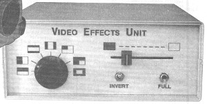
A "Full" switch is provided to show the picture when the unit is faded - this is useful for finding the beginning of the next section once the recording machine is paused.
The unit offers seven wiping effects, all of which are also available in inverted form giving a total of fourteen, these are illustrated in fig **.
As described this unit does not fade the sound, however it would be a simple matter to add a second slider control next to the existing one, and operate both simultaneously. Further comments on this option are given later.
The unit only allows the wiping of one video input to black. Due to sync problems it is not possible to mix two video signals without incorporating the expensive digital techniques contained in commercial products. Broadcasters and professionals use a gen-lock system where all equipment is controlled by one external sync generator, however domestic video equipment does not support this system. In any case mixing two signals would require three video recorders, which is probably excessive by domestic standards!
The Works
The complete circuit diagram is shown in fig ** and fig **. Although this may initially appear complicated, the operation is reasonably straightforward.
On the circuit diagram and in the following description, a "-" after a signal name indicates that the line is active low.
The unit works by selectively blanking the picture. To achieve this, parts of the video signal are replaced with a voltage level corresponding to black. Monostables and control logic are used to select the portions of the signal to blank.
The video signal enters the unit via SK1, and is terminated by R1. The circuit around TR1 removes the sync portion of the video signal, C2 and R5 convert this to short pulses, which are buffered by TR2. The longer frame sync pulses are able to pass through R9 and C4, and are buffered by TR3.
The voltage from the control pot is buffered by half of IC11. This is then inverted by the second part of IC11, and the level reduced to give an output range of 11V to 5V for an input range of 0V to 11V. Note that the pot is a dual device with the tracks wired in anti-parallel, the front panel Invert switch selects which wiper is connected to IC11.
The two control voltages are used to control the delay of monostables IC's 2,3,5 & 6. These monostables are based around the 7555 IC, which is the CMOS version of the popular NE555. This device was chosen because its delay can be adjusted by an external voltage on pin 5 - this alters the threshold voltage. The level of the control voltage reaching each IC is adjustable over a limited range by the 10K preset pots, this is to allow for component tolerances.
However since the charging waveform on the timing capacitor is exponential, the control voltage does not change the delay linearly. To overcome this, the timing capacitor is charged from a constant current source, giving a linear sawtooth waveform and therefore linear control of the delay. The constant current source, consisting of a transistor, two diodes and two resistors, gives a (reasonably) constant 60uA charging current for the timing capacitor.
The above arrangement is repeated four times. In the case of IC3 and IC6 an additional transistor can switch a second resistor in parallel with the constant current control resistor, increasing the current and hence reducing the delay. This facility is used for those patterns where the top and bottom, and/or both sides of the screen are blanked, and the delay from the left or top only has to reach the centre.
IC2 and IC5 are controlled from the reduced and reversed control voltage from the second half of IC11. This gives a control range from the right or bottom of the screen to the centre.
Two additional monostables (IC1 and IC4) give fixed delays for the left and top of the screen. These are used to ensure that the colour burst and frame sync pulses are not blanked.
We now have all the control signals, the next stage is to select which of these are used, and how they are used, to achieve the selected blanking pattern. This is the job of the Control Logic, which is in turn controlled by the Control Switching.
The first two gates in IC7 (an exclusive NOR gate) are controlled by an INVERT- line from the control switching, and allow the signals from the top and left delay monostables to be inverted. The four gates of IC8 (NOR) allow each of the outputs from the monostables to be individually selected. The outputs from these are combined with a four input NOR gate, IC9.
The output of this passes to the third gate in IC7, which is controlled by the INVERT- signal. This is followed by the last gate in IC7, which is controlled by the front panel Invert switch. IC9 combines the output from this with the fixed delay signals from IC1 and IC7, and the inverted signal from the Full switch, to form the BLANK- signal.
The operation of the above logic is controlled by the mode switch, via D12-D22 act as basic logic. The truth table of switch position against control logic levels is shown below. Note that the control lines are pulled high (1) by resistors, the diode logic and switch pull the appropriate lines low (0).
Mode Switch Position
1 2 3 4 5 6 7
---------------------------------------
TOP EN- 0 1 0 1 0 0 0
BOT EN- 1 1 0 1 1 1 0
Control LFT EN- 1 0 1 0 0 0 0
Line RGH EN- 1 1 1 0 1 1 0
T/L FULL 1 1 0 0 1 1 0
INVERT- 1 1 0 0 1 0 0
The BLANK- signal mentioned earlier controls a changeover analog switch arrangement that switches either the complete video signal, or a DC voltage equivalent to Black level, to the output buffer amplifier. The changeover analog switch is constructed from a pair of gates in the 4066 (IC10), by using a third gate as an invertor. The incoming video signal is held with the negative tips of the sync pulses at about 0V by D11 and C20. VR5 sets the DC level for the blanked signal.
The circuit requires a regulated supply of 12V DC at 50mA, this is derived from a 7812 regulator circuit. C29-C33 are decoupling capacitors that are distributed around the PCB.
Construction.
The circuit is constructed on a single sided PCB, 157mm x 134mm. The component overlay is shown in fig **.
The 31 link wires should be fitted first, followed by the other components in the usual size order. D11 is a germanium device and extra care should be taken to ensure it does not get too hot. The holes for the off-board connections (shown as SK1 to SK7) should be fitted with terminal pins or suitable 0.1" pitch connectors.
The PCB was originally designed for low cost ceramic disk capacitors. However when testing the prototype, it was found that these were not suitable for the monostable timing components. C7, C9 and C11 should be polystyrene types, the leads of these may need to be formed to fit the PCB. C13, C15, C16, C18 and C19 must be polyester or mylar types, polyester types are available in 0.2" pitch to suit the PCB.
IC sockets may be used for the IC's, however the IC's are fairly cheap and could be soldered directly into the PCB if preferred. In this case they should be fitted last and due care taken to avoid static damage.
The prototype was constructed in a plastic case, 190mm x 165mm x 68mm. A suitable overlay for the front panel is shown if fig **, this may be photocopied and fixed to the front panel with clear self-adhesive vinyl ("sticky-backed-plastic" as Blue Peter call it!).
The interwiring is shown in fig **. Screened wire should ideally be used for the video signals, but since the cable runs are short this is not essential. Normal hookup wire or coloured ribbon cable may be used for the remainder of the low voltage connections. Take care when soldering to the slider pot as the connection pins are not very tough!
No mains power switch or fuse are necessary, however a three-amp fuse must be fitted in the mains plug. A suitable cable clamp should be fitted to the case where the mains lead enters. The mains cable may then be connected directly to the transformer tails with a choc-block connector. Since the unit is not earthed, the transformer must be fitted with nylon screws.
Testing.
Initially set VR1-VR4 fully clockwise, and VR5 to the centre position. Set the slide control fully to the left, the Effect switch to position one, the Full switch to the off (upper) position and the Invert switch to the lower position. Connect the unit between two video recorders and connect a television or monitor to the second video recorder.
Switch the unit on. If a test meter is available check the regulated supply is indeed 12V. The picture on the TV should be blank. Move the slider to the right, and more of the picture should appear as it is moved.
With the slider fully to the right, adjust VR4 to remove the whole black section at the bottom of the screen. If the control is adjusted too far the picture will flicker and may roll. Set the control just before the onset of the flickering.
Now set the Effect switch to position two, and adjust VR2 for no blanking on the right side of the screen. If this control is adjusted too far alternate lines on the screen will be blank, adjust to the point just before this occurs. Check that with the slider fully to the left the whole picture is blank, careful adjustment of VR2 should give the desired results at both ends of the slider's range.
Set the Invert switch to the upper position and the Effect switch to position three and adjust VR3 as described previously. Set the Effect switch to position four and adjust VR1. In both cases check the operation of the slider control.
With the screen partially blanked, adjust VR5 so that the blanked portion is black. If a testcard is available (try unused satellite channels) this will provide a suitable black reference. If VR5 is set too far anti-clockwise the picture may roll or pull on some settings of the controls.
Finally check the operation of all the controls. If the unit was constructed with care no problems should occur.
Options.
The following suggestions are aimed at experienced constructors, and have not been tested by the author.
This unit does not fade the sound. However if a second dual slide pot (10K Log) may be placed next to the existing one on the front panel, the two controls may then be operated simultaneously. This second control is then wired as a passive attenuator in the audio line(s) between the two video recorders. Some constructors may like to construct a mechanical linkage between the two, and have only one control knob.
A possible problem with this arrangement is that the automatic recording level system in the video recorder might try to raise the volume while it is faded. This point should be checked with the equipment being used.
Many people will probably carry out their video editing from the sofa with the aid of the remote controls. The front panel controls on this unit may be mounted separately from the remainder of the circuit, and connected by a length of thin 12 core cable. Not true remote control perhaps, but better than lying on a cold floor for hours!
If a second video monitor is available it may be useful to connect this in parallel with the input to this unit, so that the input and output can be monitored independently. In this case R1 should be omitted since the line will be terminated by the input impedance of the monitor. The input impedance if this unit without R1 will be about 10K. This does not apply if the second monitor is a television connected via the aerial socket.
In Use.
The unit is connected in the video link between two video recorders, or between a camcorder and a video recorder.
In normal use the effect required is selected, and the slider is set to the left. The recording unit is set to Record/Pause mode. When the section to be recorded is played, the pause should be released and the slider moved steadily to the right. When the end of the section approaches the slider is moved steadily back to the left and the recording machine is paused again. A new effect may then be selected and the whole process repeated.
When the Effect and Invert switches are operated the picture may flicker. If the same effect is used at the beginning and end of a section then no problems will be experienced. However if either of these switches need to be operated while recording, the Full switch should be turned on first, and off again afterwards.
The Full switch may also be useful for monitoring the searching on the playback machine, while the recording machine is paused.
Your holiday videos may never be the same again!
Parts.
Resistors (all 0.25W 5%)
R1 82R
R2,3 27K
R4,8,13,17,20,24,28 22K
R5 5K6
R6,44 1K0
R7,9,18,29 4K7
R10,16,21,52 15K
R11,12,14,15,19,22,23,25,
26,30,32-39,42,43,51,53 10K
R27 12K
R20,40 100K
R31,41 220K
R45 100R
R46 2K2
R47 120R
R48 150R
R49 680R
R50 18K
VR1-5 10K Horiz Preset
Slide Control 10K Dual Lin Pot
Capacitors
C1 220n
C2,23 220p
C3,22 100u 16V
C4-6,8,10,12,14,17,24 10n
C7,9,11 470p
C13,16,19 47n
C15,18,21,26,27,29,30-33 100n
C20 470n
C25 2200u 25V
C28 220u 16V
Semiconductors
IC1-6 ICM7555
IC7 4077
IC8 4001
IC9 4002
IC10 4066
IC11 CA3260
IC12 7812
TR1,4-9,11 BC558
TR2,3 BC548
TR10 BF244A
D1-10,12-22 1N4148
D11 OA47
D23,24 1N4001
PCB, Case, 1 Pole 12 Way switch, DPDT Toggle Switch, SPST Toggle Switch, Two BNC Sockets, 12-0-12V 250mA Transformer, Mains Flex, Cable Clamp, Knobs.
The plastic case used for the prototype is made by Bafbox, and is available from RS/Electromail, stock no 506-788.
The slide control pot was supplied by Maplin, note that M2 x 12mm countersunk mounting screws and 6mm spacers must be purchased separately.
The non-polarised capacitors should be 0.2" pitch, others sizes may be suitable if the leads are bent. See the notes in the construction section regarding capacitor types. Low cost ceramic disk capacitors are suitable.
Since the unit is likely to be permanently connected to the mains, a 250mA transformer should be used. The 100mA types run fairly hot at a continuous 50mA.