 You
know the situation - you've spent all day knocking channels and holes in the
plaster, and burying the cables. It's now nearly midnight, and you're
just fitted the socket plates and turned the power back on. You could
get the multimeter out and check it's all wired correctly, but you really can't
be bothered. After all you joined the three wires to the right terminals
didn't you? And the earth wire didn't come away when you screwed the plate
in place, did it? Can you be certain it's correct?
You
know the situation - you've spent all day knocking channels and holes in the
plaster, and burying the cables. It's now nearly midnight, and you're
just fitted the socket plates and turned the power back on. You could
get the multimeter out and check it's all wired correctly, but you really can't
be bothered. After all you joined the three wires to the right terminals
didn't you? And the earth wire didn't come away when you screwed the plate
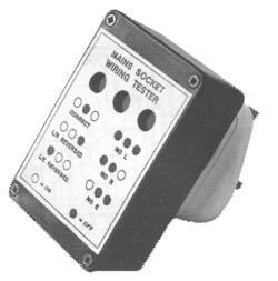
in place, did it? Can you be certain it's correct?Wouldn't it be useful to have a little whatsit that you can plug into the socket to tell you instantly if it's wired OK or not. A professional electrician would have a test plug with three neon lights to do just this. However these items are not readily available in DIY stores. You can get them from electrical trade counters and wholesalers, but they cost around £40, which is rather expensive for the occasional DIY job.
The testplug described here does exactly the same job as the professional ones - and works the same way. However this one uses about eight pounds worth of readily obtainable bits.
The testplug is also useful for checking multiway adaptors and extension leads. Earth faults are surprisingly common with these, and will normally pass unnoticed until the worst happens.
Circuit Description
The complete circuit diagram is shown in figure 1.
The neon lamps will illuminate once the voltage across them reaches about 60V. The current required is less than 1mA, which is controlled by the series 220K resistor.
Three sets of neon and series resistor is connected between the three pins on a 13A plug. With a correctly wired socket, the Live to Neutral and Live to Earth neons only, will light.
The additional 100K resistors in parallel with each neon prevent the neons lighting if there are two in series. This would happen if the Earth or Neutral wire was not connected.
This unit can reveal all common socket wiring errors, except Neutral and Earth reversed. Since these two lines are at almost the same potential this is impossible to detect with a simple testplug.
Construction
The neons and resistors are mounted on a small pcb. The component positioning is shown in figure 2.
Before fitting the neons, attach a white self adhesive label to the pcb, with the bottom edge 5mm above the neon holes. This is to reflect the light from the neons. Bend the neon leads 5mm from the body before fitting into the PCB. Although the PCB assembly is straightforward, please take care to avoid errors.
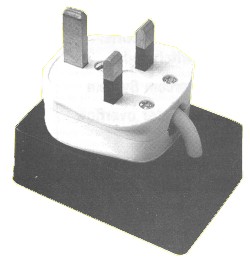 The PCB is fitted
into a small plastic box (type T3), which is mounted on the back of a normal
13A plug. The original plan was to use one of the small cases fitted with
plug pins, intended for power supplies. However these are not readily
available with a metal earth pin.
The PCB is fitted
into a small plastic box (type T3), which is mounted on the back of a normal
13A plug. The original plan was to use one of the small cases fitted with
plug pins, intended for power supplies. However these are not readily
available with a metal earth pin.Select a 13A plug with a flat back (many are slightly curved). Ideally this should be made of the softer unbreakable plastic, since this is easier to drill. The plug used on the prototype was branded PMS.
Remove the back from the plug, and drill two 3mm holes in convenient positions. On the prototype, one hole was above the cord grip and the other was in the void between the Neutral and Earth pins.
Position the plug back on the base of the box, about 5mm down from the top, and mark the positions of the holes. Drill the holes and fix the plug back in place with two 6mm long M3 pan-head screws and nuts. If necessary some suitable adhesive may be used to reinforce the joint. Drill a hole in the back of the box, below the plug cable entry position, to suit the three core being used.
Take a 150mm length of this flex and connect one end correctly to the plug base. Fit a 1 Amp fuse in the plug. Feed the other end of the wire through the hole in the box, and screw the plug together. Fit a cable tie around the cable on the inside of the box. Strip the outer insulation back, inside the box.
Position the PCB centrally inside the box lid. Mark and drill the four 3mm fixing holes and three 6mm holes for the neons to show through. The fixing holes should be countersunk from the outside. A piece of neutral (or red) filter material must be glued inside the case over the holes.
Note that, contrary to the information in the catalogue, the filter material supplied by Maplin/MPS cannot be cut with scissors, as it will crack. Use a junior hacksaw.
Cut the wires to length and solder to the PCB as shown on the component overlay. Mount the PCB with 10mm M3 insulated spacers. Use countersunk screws in place of those supplied with the spacers on the outside of the box. Ensure that any metal parts outside the box are not connected to any metal parts inside the box.
To prevent the light from one neon showing in another window, two pieces of the outer insulation from the mains cable may be positioned between the PCB and the front panel, between the neons. The insulation should be the right diameter to be a snug fit, but if it is too loose it can be fixed to the PCB with superglue.
When fitting the lid onto the box, ensure the wires do not lay underneath the PCB. A suitable front panel overlay is shown in figure 4. This may be photocopied onto a self-adhesive label, covered with clear self-adhesive vinyl and fixed to the case. Note that the label will cover the heads of the fixing screws.
Adaptations for Overseas Use
Overseas readers may be able to adapt this design to suit their local supplies by attaching the case in some way to the rear of an appropriate type of mains plug. If the mains supply voltage is around 120V the 220K resistors should be reduced to 68K.
Note that this unit will only give the correct indication if the neutral line is at a similar potential to earth. It cannot be used in countries where the supply is floating or where the mid-point of the supply is earthed. Check this with a qualified electrician or your local electricity supply company if in any doubt.
Testing
NEVER OPERATE THIS UNIT UNLESS IT IS FULLY ASSEMBLED. MAINS VOLTAGE CAN KILL - PLEASE BE VERY CAREFUL!
If the unit is correctly assembled there is no reason why it should not work first time. If a residual current (earth leakage) circuit breaker is available, it would be sensible to plug the testplug into this for initial testing. Assuming your socket is wired correctly, the outer two neons should light and the centre one should remain off.
If you wish to try the various fault conditions, this can be achieved by altering the wiring in one end of an extension lead. Switch the mains off and unplug before touching any connections, and replace all covers before switching back on. Be sure to rewire the extension lead correctly when finished.
In Use
Using the testplug is straight-forward. Simply plug it into the socket, and if the outer neons light the socket is wired correctly. If any other combination of neons illuminate, there is a fault with the socket which must be investigated.
A faulty socket must not be used under any circumstances. If you are not able to correct the wiring immediately, cover the socket with insulation tape and affix a suitable notice to prevent anybody attempting to use it.
When testing extension leads and multiway adaptors, wiggle the test plug around and check that the neons do not flicker. Many multiway adaptors have poor earth contacts which can give intermittent operation.
Never take any chances with mains electricity. If you are in any doubt, please seek expert advice.
Parts List
R1,3,5 100K 0.6W Metal Film Resistor
R2,4,6 220K 0.6W Metal Film Resistor
N1,2,3 Wire Ended Neon Lamp
13A Plug (see text)
1A 25mm Fuse
Plastic Box Type T3
Filter Material Neutral
3A Three Core Mains Flex
M3 Insulated Spacers 10mm
M3 6mm Countersunk Screws
M3 6mm Pan Head Screws
M3 Nuts
Cable Tie
PCB