Transmitter
Supply voltage - 9V
Standby current - less than 2uA
Operating current - 50mA typical
Battery type - Alkaline PP3
Operating range - 5 metres typical
Number of channels - 4
PCB size - 66mm x 53mm
Overall size - 108mm x 59mm x 24mm
Weight - 100 grams including battery
Motherboard
Supply voltage - 230V AC, 50Hz
Supply current (all channels off) - 35mA typical
Maximum total lamp power - 1500W
Number of control modules - up to 4
Type of control modules - Any mix of Dimmer and Switch modules
PCB size - 135mm x 100mm
Dimmer Module
Maximum lamp power - 400W
Type of load - resistive only
Control operations - switching and dimming
Number of remote channels used - 1
Operating methods - remote control and touch sensor
Link selectable options - 3 operation modes (see text)
PCB size - 100mm x 25mm
Switch Module
Maximum load power - 600W
Type of load - any
Control operations - switching
Number of remote channels used - 1
Operating methods - remote control and touch sensor
Link selectable options - Toggle or Momentary mode
PCB size - 100mm x 33mm
WARNING - This unit operates at potentially lethal mains voltages.
Introduction
Many household items are now supplied with remote control handsets - all designed to encourage laziness! However, to adjust the room lighting it is usually still necessary to get up and do it manually. This is probably because the lighting was specified by the house builder, and most householders are understandably reluctant to alter it. Some single channel remote control dimmers are becoming available, but they are still rather expensive.
The system described here allows up to four channels of lighting to be remotely controlled. It has been designed to be relatively inexpensive, without compromising safety and reliability.
Such a system could be helpful for persons who cannot move as easily as they would like, such as the elderly or disabled. If necessary in individual cases, the remote handset may be housed in a larger box with suitable push buttons.
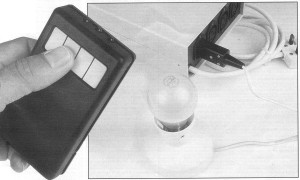
The prototype was used as a stand-alone system, connected to table lamps and a desk fan. Ambitious constructors could consider incorporating the unit into the household wiring, if they are satisfied that the installation will comply with the relevant wiring regulations.
System Overview
The receiver consists of a motherboard, onto which are mounted separate control modules for each channel. Two different types of control module are available. The first, and probably more popular type, is the dimmer module. This allows up to 400W of lighting to be switched or dimmed from a single button on the remote handset. This module can only be used with resistive loads such as normal incandescent light bulbs. It cannot be used with inductive loads such as fluorescent lights, low voltage transformer powered lighting etc.
 For inductive loads
the switch module may be used. This allows switching only, and can
be used with any type of load up to 600W. As well as lighting (including
fluorescent and transformer powered), it could also be used to control
other loads such as fans, low power heaters and video game consoles.
For inductive loads
the switch module may be used. This allows switching only, and can
be used with any type of load up to 600W. As well as lighting (including
fluorescent and transformer powered), it could also be used to control
other loads such as fans, low power heaters and video game consoles.This module can be configured to either of two modes of operation by means of a single link. Probably the most useful is Toggle, whereby the load is switched alternately on and off each time the remote button is operated.
In Momentary mode the load is only driven while the button is pressed. This may be useful for operating outdoor security lights, or for activating a bell or sounder to call for assistance.
Each of the four channels may also be operated by touch sensors on the receiver box - very useful if the handset gets lost or the battery is flat! The remote control handset is built into a proprietary case with built-in buttons and battery compartment.
Infra-red Communication Link
If I was designing this system two or three years ago, I would have specified the MV500, MV601, SL486 and SL490 ICs for the remote control system. However GEC-Plessey have now classified these useful devices as obsolete which means that, although supplies may still be available, they are not recommended for use in new designs.
To further complicate the situation, there appears to be no other devices available to carry out similar functions. This is probably because most equipment manufacturers use their own custom remote control ICs to ensure that their coding is different from every other manufacturer. Thus the demand for standard remote control ICs has declined.
In this design I am using the HT12E and HT12D devices from Holtek. These result in a design that is more complicated and gives slightly reduced range compared to that obtained with the GEC-Plessey devices. However I have very little choice - the Holtek devices are about the best of a fairly poor range of available ICs.
This should not be taken as a criticism of the devices themselves, since they are intended for security coding systems (such as car alarms and cordless telephones) rather than infra-red remote controls.
Holtek HT12E and HT12D
The HT12E encodes the 12 bit data on it's 12 data input lines (A0 to A11), and then serially transmits it when the transmitt enable pin is taken low. The data output appears on the D-OUT pin. The data is transmitted four times in succession. The data consists of differing length positive going pulses for 1 and 0, the pulse for 0 being twice the width of the pulse for 1.
The HT12D receives the data from the HT12E on its D-IN pin. If the data received matches the levels on the A0 to A7 pins four times in succession, the valid transmission (VT) pin is taken high. The data on pins A8 to A11 of the HT12E appears on pins D0 to D3 of the HT12D. Thus the device acts a receiver of 4 bit data (16 possible codes) with 8 bit addressing (256 possible channels).
The third device in this family (not used in this design) is the HT12F. This is similar to the HT12D, except that the levels on all 12 data pins must match those on the HT12E for the VT line to be taken high. This device acts as a single channel receiver with a 12 bit address (4096 possible channels).
The devices contain an internal clock, the frequency of which is set by a single external resistor connected between the OSC1 and OSC2 pins. The frequency of the receiver (HT12D/HT12F) clock should be approximately 50 times the transmitter (HT12E) clock. The relationship of frequency to resistance is not linear, and also depends upon the supply voltage. The clock resistor values used in this design were obtained with reference to the graphs in the device data sheets.
The devices operate over a supply voltage range of 2.4V to 12V, with a typical standby current of 0.1uA at 5V and 1uA at 10V. The operating current is under 1mA.
Transmission Problems
The Infra-red transmission medium works best with very short pulses, and is ideally suited to coding systems that rely on the presence or relative timing of pulses. This is the type of coding used in most commercial pieces of equipment, as well as by the obsolete GEC-Plessey devices mentioned earlier.
Infra-red does not lend itself so well to pulse width based systems such as the Holtek devices used in this design. This is partly because the transmitting LEDs must be operated at currents of around 1.5A to give a reasonable range, and this sort of current can only be sustained for very brief periods to avoid damaging the LEDs and to keep the average current consumption to a reasonable figure. Also the receiving photo-diode and amplifier IC are designed for very short pulses, to prevent interference from lower frequency light variations such as mains fluorescent lighting at 50Hz.
In this design the variable width pulses from the HT12E are used to control a higher frequency pulsing circuit which in turn drives the LEDs. At the receiving end the groups of pulses are recombined to give the variable width pulses required by the HT12D.
This system works fairly well in practice although, as mentioned earlier, the range may not be as great as some commercially made remote control systems. The prototype operates reliably up to about 5 metres (16 feet), which should be ample for an average sized room.
Remote Control Handset Circuit Operation
 The
handset circuit diagram is shown in figure 1. The HT12E data lines
A0 to A7 are taken high. This is because the IC outputs shorter
pulses for a logic 1 than for a logic 0. Thus the output LEDs are
lit for less time, giving a reduction in current consumption from the
battery.
The
handset circuit diagram is shown in figure 1. The HT12E data lines
A0 to A7 are taken high. This is because the IC outputs shorter
pulses for a logic 1 than for a logic 0. Thus the output LEDs are
lit for less time, giving a reduction in current consumption from the
battery.If this coding causes problems with other pieces of equipment, some of the lines may be taken low by cutting the appropriate PCB track and linking pins 8 and 9 of the IC. Obviously the tracking on the motherboard must be modified in a similar manner. The PCB tracking of both boards have been designed to make this modification easy.
The remaining four data lines are connected to the four channel push buttons, so that one line goes low when the appropriate button is pressed. The four push buttons are also gated to the active low transmit enable (TE) line via diodes D1 to D4 and R6.
U2:A (4093), and surrounding components form an oscillator running at about 30KHz. This oscillator only operates while one of the push buttons is held, due to U2:B. D5 and R7 modify the mark-space ratio such that the output on pin 3 is low for about 20% of the time. This is inverted by U2:D and then gated with the data output (D-OUT) from U1 by U2:C.
The output LEDs (D6, D7 and D8) are driven by Q2, which is in turn driven by Q1. R13 limits the LED current to about 1.5A, although the value could be reduced at the expense of battery life if extra range is needed. C2 provides the power for these brief high current pulses, while D9 protects the circuit if the battery is connected incorrectly.
Motherboard Circuit Description
The motherboard contains the IR receiver and decoder, together with the power supply. The circuit is shown in figure 2.
D101 is the IR photo-diode and U101 (TBA2800) is the infra-red amplifier. This IC contains three stages of amplification, the first of which has an automatic gain adjustment system to cope with varying signal and ambient light levels. The second amplifying stage simply provides further amplification, and the third separates the wanted signal from the general background noise. An inverting stage is also provided to give both positive and negative outputs.
The overall gain of the IC is quoted as 70dB, and the typical current consumption is 1mA at 5V.
C103 and C104 are the coupling components between the amplifying stages. The values of these have been chosen to give good coupling at the IR transmission frequency, while rejecting lower frequency noise and interference. C102 is the filter component for the automatic gain control of the first amplifier in U101. The power supply to U101 is decoupled by R101, C101 and C105.
The output of U101 will be groups of pulses, similar to those transmitted by the handset. D104, C106 and R102 recombine these, but the rising and falling edges of the resulting waveform are rather imprecise. U104 is configured as a comparator with hysteresis to produce a tidy waveform for U102.
U102 is the HT12D remote control decoder, which was discussed earlier. The valid transmission (VT) output is inverted by Q101, and gated with the data outputs (D0 to D3) by U103. This gating is necessary because the data outputs of U102 remain when the transmission finishes. The appropriate output of U103 goes high when a button is pressed on the remote control handset, and the signal passes to the appropriate lamp control module.
As the total power consumption of the control circuitry including four modules is only about 10mA at 5V, a basic mains-derived power supply arrangement is adequate. The control circuits are connected directly to mains live on the lamp control modules in any event, so there would be no advantage in using an isolated supply from a mains transformer. The mains input is connected to TB101.
In circuits such as this a capacitor (C109) is used to drop the excess voltage as, unlike a resistor, it does not dissipate any power due to the 90 degree phase shift. R103 limits the surge current at switch-on, and R104 discharges C109 when the unit is disconnected from the mains. The +0.6V/-5.6V pulses on D102 are rectified by D103 and smoothed by C110 to give a stable 5V supply, at up to about 15mA. SUP101 is a surge suppressing component.
The test link allows the power supply to be tested (before the control modules are fitted) without being connected to the remaining circuitry. J101 to J120 are the connections to the control module boards, and TB102 to TB105 are the connection points for the lamps being controlled.
Dimmer Module Circuit Description
The circuit, shown in figure 3, is based around the Siemens SLB0586A touch dimmer IC. This IC permits the design of fully electronic dimmers for resistive load incandescent lamps, operated by a single touch sensor or remote control channel. The lamp brightness is set by phase control. The IC contains a phase-locked loop which is synchronised to the mains frequency.
A digitally determined period of approximately 50mS ensures a high degree of immunity to interference in the control inputs, while allowing almost instantaneous operation. The device can distinguish between turning On/Off and dimming by the duration of the control input signal period. A brief pulse (50 to 400mS) will switch the light on or off.
If the input is operated for a longer period the lamp brightness will be varied up and down for as long as the input is operated. The complete cycle takes 7.6 seconds (eg bright-dim-bright) and stops at the chosen brightness when the input is removed. The lamp brightness is varied in a physiological-linear manner to enable easier setting at lower brightness levels.
There are three modes of operation, which are link selectable. In modes A and C the lamp always comes on at full brightness, over a 380mS soft-start period. In mode B the lamp comes on at the same brightness as when it was turned off. In mode A, a dimming operation will start in the same direction as the previous dimming operation, while in modes B and C the dimming will start in the opposite direction. For mode A, join LK203 to LK202 on the PCB. For mode C join LK203 to LK201, and for mode B leave LK203 unconnected.
The supply to U201 is decoupled by R208 and C204. R201 and C201 are the integration components for the internal phase locked loop. L201 and C203 are EMI suppression components. J206 is the signal from the remote control decoder circuit on the motherboard and J203 is the connection point for an optional local touch sensor. R204 and R205 limit the touch sensor current to about 25uA, which is so low that it cannot be felt. For safety the two separate resistors must not be replaced by a single component. Mains Neutral is not required by this module, but the terminal (J205) is provided for compatibility with the Switch module.
The recommended triac is a BT137-600 or a T410-600. The author does not recommend the use of the C206, C216 or C226 range of devices as he has found these to be unreliable in several different applications.
Switch Module Circuit Description
With the dimmer module described previously, the triac is triggered just once in each half cycle of the mains. Although the trigger current is about 20mA, it only occurs for a brief period so the average current consumption of the circuit remains low.
The Switch module is designed to drive inductive and capacitive loads, as well as resistive. Therefore the triac ideally needs to be driven continuously for the complete mains cycle. The current required for this would be 20mA per module, giving a total of 80mA if four switch modules were fitted. This sort of current cannot be obtained from the basic mains derived power supply arrangement used, so a method of reducing the average current consumption is needed.
The solution is very similar to that employed in the remote control handset. A fast chain of brief pulses are used to drive the triac, such that when the triac switches off (due to the load current passing through zero) it is almost immediately retriggered.
Referring to the circuit diagram in figure 4, U301:A is configured as a free running oscillator at a frequency of about 4KHz. R302 and D301 set the mark-space ratio so that the output is high for 20uS and low for 230uS. When pin 6 of U301:B (ON) is high, the pulsed signal is passed to the triac via Q302 and Q301. The triac therefore receives 20mA trigger pulses while the average current consumption is under 1mA. C303 decouples the supply and supplies the brief current pulses, while C302 and L301 are EMI suppression components.
U301:D and U302:B form the zero-crossing detector. The mains is squared by U301:D, the output of which is a 50Hz square wave. R306 and C304 filter out any high frequency noise on the mains that might otherwise cause erratic triggering. U302:B is a D-type flip-flop, the Q output of which latches to the logic state on the D input when the CLK input receives a rising edge. Thus when the D input changes state, the change is transferred to the Q output on the next falling zero-crossing point. The circuit ensures that the load is only switched at the zero-crossing point to minimise interference, and that the load always receives an equal number of positive and negative half cycles to avoid magnetising the core of inductive loads.
If LK301 is connected to LK302 the circuit is in momentary mode. The control input is then passed directly to U302:B, so that the load is only powered when the remote control button is pressed.
When LK303 is connected to LK302, U302:A is bought into the circuit. By connecting the NOT-Q output to the D input the device acts as a divide-by-two circuit. Thus the output (Q) changes state each time the CLK input receives a rising edge. The result is that the load is switched on by the first button press, off by the second etc. C305, R305 and D305 ensure that both halves of U302:A are reset when the power is switched on, so the circuit always starts with the load turned off.
The circuit around U301:C is the touch sensor input. The high impedance 50Hz signal caused by grounding J306 via the human body, are rectified by D310 and smoothed by C306. This signal is sufficient to drive the high impedance input of U301:C. The output of this circuit is combined with the remote control input (J305) by the diode OR gate (D306, D307 and R307). R310 and R311 limit the touch sensor current to about 25uA, which is so low that it cannot be felt. For safety the two separate resistors must not be replaced by a single component.
Handset Construction
 The
circuit is constructed on a single sided PCB (see figures 5A and 5B),
which is designed to fit into the recommended case. The four corner
holes may need to be enlarged to accommodate the fixing screws, and the
two corners closest to the LEDs may need to be chamfered slightly as shown.
The
circuit is constructed on a single sided PCB (see figures 5A and 5B),
which is designed to fit into the recommended case. The four corner
holes may need to be enlarged to accommodate the fixing screws, and the
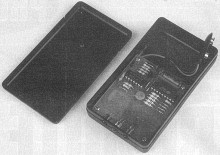
two corners closest to the LEDs may need to be chamfered slightly as shown.The PCB construction is generally straight-forward, but the following points should be noted. C1 and C2 must be laid flat against the PCB as shown, and may be held in place with a small amount of suitable glue (eg Evostick) to stop them rattling. The ICs may be fitted in sockets if desired, although these were not used on the prototype. The links should be made with 24SWG tinned copper wire or component lead off-cuts.
The four switches must be fitted on the solder side of the PCB. Depending on the type of switches used, it may be necessary to raise the edges of the switches closest to the LEDs slightly away from the PCB to ensure they are operated positively by the buttons fitted into the case. The three LEDs protrude through holes in the case so it may be easier to fit them after the case has been drilled. One hole should be central, and the others 10mm either side. The hole diameter is 5mm. The LED cathode is normally indicated by a flat on the side of the body.
The battery lead should be soldered to the terminals shown, with the red wire to the positive terminal and black to negative. The lead is then knotted around one of the PCB mounting pillars in the case, when the PCB is being fitted.
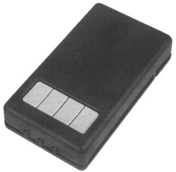
The case is supplied with button assemblies for one. two and four button systems. Normally the four button assembly would be used, but if you are building a one or two channel system you could use a suitable button assembly and omit the appropriate switches on the PCB. The PCB is fitted into the case with the screws provided. If the screws are too long they can easily be shortened with a large pair of wire cutters. Finally fix a thin piece of foam into the case to prevent the battery from rattling, and screw the back in place.
Handset Testing
Clip one battery lead clip onto one battery terminal. Connect a test meter, set to the 200mA DC range, between the other battery lead clip and the other battery terminal, so that the meter is in series with the battery. After an initial surge the meter should read zero, or possibly 1mA. Switch down to the 2mA range to obtain a more precise reading, which should be less than 0.010mA (10uA). The reading may initially be higher than this, and gradually reduce as the chemical composition of C2 reforms.
Set the test meter back to the 200mA DC range, and press one of the remote control buttons. With a fresh alkaline battery the reading should be between 40mA and 60mA. If the readings obtained vary greatly from these, the cause should be investigated. If all is well the battery may be fitted properly and the cover clipped into place.
Motherboard Construction
The motherboard is constructed on a single sided PCB, which is shown in figures 6A and 6B. Do not fit anything into the module positions (pads J101 to J120), or in the test link position (TP101 to TP102) at this stage.
Fit the terminal blocks (TB101 to TB104) with the wire entries towards the edge of the PCB. C103 must be a Class X or X2 rated component, suitable for direct connection across the mains. D101 is be fitted with the curved side towards the edge of the PCB as shown.
A terminal pin (Veropin) should be fitted in the pads at each corner of the rectangle around U1 and surrounding components. These are used to hold a screening can made from a 30mm wide strip of tin sheet. Take care when cutting this as the edges can be very sharp.
A small aperture is needed so that the IR can reach D101. It may be easiest to join the tin sheet at this point. The tin plate can easily be soldered to the terminal pins and itself with a larger soldering iron (above about 30W).
It is advisable to fit a lid to the screening can. Do not do this until the unit has been tested, in case you need to get inside! Clean the PCB with suitable solvent to remove any flux residues.
Motherboard Testing
 WARNING. DURING
THIS TESTING PROCEDURE THE ENTIRE MOTHERBOARD IS LIVE AT MAINS POTENTIAL.
SWITCH OFF AT THE MAINS BEFORE TOUCHING THE MOTHERBOARD, TEST METER OR
ANYTHING ELSE CONNECTED TO IT. FAILURE TO HEED THIS WARNING MAY
RESULT IN A POTENTIALLY FATAL ELECTRICAL SHOCK. THE USE OF A RESIDUAL
CURRENT CIRCUIT BREAKER (THE TYPE USED FOR GARDEN POWER TOOLS) IS RECOMMENDED.
WARNING. DURING
THIS TESTING PROCEDURE THE ENTIRE MOTHERBOARD IS LIVE AT MAINS POTENTIAL.
SWITCH OFF AT THE MAINS BEFORE TOUCHING THE MOTHERBOARD, TEST METER OR
ANYTHING ELSE CONNECTED TO IT. FAILURE TO HEED THIS WARNING MAY
RESULT IN A POTENTIALLY FATAL ELECTRICAL SHOCK. THE USE OF A RESIDUAL
CURRENT CIRCUIT BREAKER (THE TYPE USED FOR GARDEN POWER TOOLS) IS RECOMMENDED.Connect a length of two core mains cable to TB101, with the live (brown) wire to the terminal closest to FU101. Connect the other end to the mains, such that it can be readily switched on and off. Do not switch on yet.
Solder a short piece of tinned copper wire to TP101 (one of the test link pads). Connect the positive terminal of your test meter to this wire, and the negative terminal to the screening can. Test leads fitted with crocodile clips are essential here. Set the meter to the 20V DC range. Place the PCB on a clean dry insulated surface - a plastic videocassette box is ideal.
Ensure you cannot inadvertently touch anything, and then switch on the mains. The meter should read between 4.7V and 5.5V. Switch off, and wait a few seconds for C103 to discharge. The meter may continue to read a voltage, or may drop slowly, due to the charge stored in C110. This is not cause for concern.
Fit the test link between TP101 and TP102. Solder short pieces of tinned copper wire into the pads marked J101, J102, J103 and J104. Connect the positive meter terminal to J101 (leave the negative on the screening can). When you switch the mains on the meter should read below 0.5V. Hold the remote control about two metres away and point it towards the curved face of D101. Push the left button and the meter should read at least 4.5V. Release the button and the reading should drop back to below 0.5V. Repeat this for the other three channels. Remember to switch off at the mains when transferring the meter connections.
If these tests are successful the motherboard assembly is working correctly. Disconnect it from the mains and remove the pieces of tinned copper wire in J101 to J104. The test link between TP101 and TP102 must remain fitted.
Module PCB Construction
Up to four module boards are needed, and they may be any mix of dimmer and switch types. The dimmer module PCB layout and artwork are shown in figures 7A and 7B, while the switch module PCB is shown in figures 8A and 8B.
Construction is mainly straight-forward, but the following points should be noted. The triacs (T201 and T301) are laid flat against the PCB (metal tab towards the board), and are held in place with M3 x 6mm panhead screws and nuts. The fuseholders may be fitted with covers if required, but these will make it more difficult to change the fuses. C203 and C302 must be Class X or X2 rated components.
On the switch module a link must be fitted either between LK302 and LK303 (toggle mode) or between LK301 and LK302 (momentary mode). The module will not operate if no link is fitted.
On the dimmer module, join LK203 to LK202 on the PCB for mode A or join LK203 to LK201 for mode C. If mode B is required leave LK203 unconnected. The three different modes were discussed earlier.
The five pads along the lower edge of the PCB (J201-J205 on dimmer module and J301-J305 on switch module) are for connection to the motherboard. They should be fitted with single pins separated from a 0.1" SIL right angle header strip.
J206 and J306 are the connections for the optional touch plates. The PCB pads should be fitted with terminal pins if touch plates are to be used.
The switch module PCB has a number of fine tracks passing close to pads, so extra care should be taken to avoid inadvertent solder bridges. When construction is complete the boards should be cleaned with a suitable solvent.
Dimmer And Switch Module Testing
Note that each of the four module positions on the motherboard relates to a separate button on the handset. Module A is closest to the IR receiver, and is the left handset button.
The module boards are fitted to the motherboard simply by inserting the five pins through the relevant holes and soldering it in place. The modules will only fit one way round, and should be mounted at 90 degrees to the motherboard.
When a module board is fitted, connect a lamp to the appropriate pair of output terminals. The neutral terminal is the one closest to the mains input terminals. Connect the system to the mains and test the module using the remote control handset.
With the dimmer module, briefly pushing the button should turn the lamp on and off, while holding the button for a longer period will cause the brightness to vary up and down. When the button is released the lamp should remain at the brightness set.
With the switch module, the results depend on the link setting. In toggle mode the lamp should alternately turn on and off each time the button is pressed. In momentary mode the lamp should stay on only while the button is held.
The final test in each case is the touch sensor input. Set your test meter to the 2mA AC range and, with the mains off, connect it between J206 or J306 and earth. When you switch on the meter should read about 0.025mA (25uA). If it reads above 0.030mA (30uA) the cause must be investigated. To avoid the risk of accidentally touching live terminals, do not be tempted to touch the touch sensor inputs until they have been connected to suitable plates on the outside of an assembled enclosure.
Final Assembly
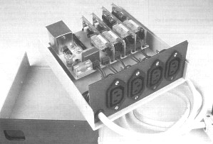
The prototype was assembled in a plastic case 165mm x 67mm x 190mm, and was not fitted with touch sensors.
The outputs were bought to four IEC sockets fitted onto the rear panel. The live and neutral to these sockets are connected to the terminals on the motherboard, and the earths are connected directly to the incoming earth. The wiring diagram is shown in figure 9. Any exposed metal parts (apart from the touch sensors) must be securely connected to earth.
The mains input cable and the connections to the sockets must be made with 6A (0.75 sq mm) wire. The unit should be fitted with a 13A plug, fitted with a fuse not exceeding 5A. If the unit is being used to control small loads such as table lamps the plug fuse should be reduced to a more suitable value, such as 3A.
The PCB is mounted in the case using insulated stand-offs. For safety reasons do not use metal spacers to mount the PCB. A suitable cutout should be made in the front panel to allow the IR to reach the sensor. This opening must be covered with a piece of red filter material, glued securely to the inside of the case. Remember that the screening can is at mains live potential.
If touch sensors are used they should be mounted on the case so that the mounting screw penetrating into the case does not come close to the PCB assembly or any live terminals. Solder tags should be positioned under the mounting screws, and connected to the PCB with insulated flexible wire. Ensure the soldered joints are secure, as a hazardous situation could occur if a wire should come adrift and make contact with a live terminal.
Another option might be to use push switches in place of the touch sensors (this would allow a metal case or panel to be used). These switches must be rated for use at mains voltages, even though the current is minimal. One side of the switch is connected to the touch sensor terminal, and the other side is connected to neutral.
Installation and Use
The loads to be controlled should be fitted with IEC plugs, and connected to the appropriate sockets on the back of the unit. If any cables need to be extended, use proper enclosed connectors - not choc-block or insulation tape!
The unit should be positioned so that the remote control can be pointed towards it from the usual sitting position. If touch sensors have been used the unit will need to be accessible.
Remember that this unit does not provide isolation from the mains. Even when a channel is switched off there may be sufficient current passing through the filter capacitors to give an electrical shock. Always disconnect the unit from the mains before altering the connections or replacing light bulbs.
Alternative Arrangements
Some constructors may wish to incorporate the unit into the household wiring. Before carrying out such an installation, it is essential to determine whether this will contravene the relevant wiring regulations and any local planning and fire regulations. Remember that such contravention may affect your home insurance and any building warranties. Advise on such matters is beyond the scope of this article.
The wiring arrangements would be similar to that shown in figure 7, although there would obviously be no IEC sockets. It will probably be necessary to provide a separate mains isolator for the unit, for safety when replacing light bulbs.
The neutral connection to the lights will probably take a different route in the household wiring, in which case only the live connection to the lights should be connected to the unit. It is still necessary to bring a single neutral connection to the unit to power the electronics.
The unit itself does not require an earth connection, but any exposed metal parts (apart from the touch sensors) must be properly earthed.
Parts Lists
Remote Control Handset
Resistors (all 0.6W 1% Metal Film)
R1 1M0 1
R2-6 100K 5
R7 10K 1
R8 47K 1
R9 4K7 1
R10 1K0 1
R11 470R 1
R12 100R 1
R13 1R0 1
Capacitors
C1 4n7 Ceramic 1
C2 1000u 16V Radial Elect 1
Semiconductors
U1 HT12E 1
U2 4093 1
Q1 BC558 1
Q2 ZTX651 1
D1-5 1N4148 5
D6-8 IR LED 3
D9 1N4001 1
Miscellaneous
SW1-4 Min Keypad Switch 4
BAT1 PP3 Alkaline Battery 1
PP3 Battery Lead 1
Case (Maplin CW26D) 1
PCB 1
Motherboard
Resistors (all 0.6W 1% Metal Film)
R101 100R 1
R102 390K 1
R103 100R 2W 1
R104 470K 1
R105,107 47K 2
R106 100K 1
R108 180K 1
R109 220K 1
R110 10M 1
R111 1M0 1
Capacitors
C101 22u 16V Radial Elect 1
C102 2u2 63V Radial Elect 1
C103,104,106 470p Ceramic 3
C105 100n Polyester 1
C107 10n Polyester 1
C108 10u 63V Radial Elect 1
C109 470n 275V AC Class X2 1
C110 470u 10V Radial Elect 1
Semiconductors
U101 TBA2800 1
U102 HT12D 1
U103 4001 1
U104 CA3160 or CA3140 1
Q101 BC548 1
D101 IR Photodiode 1
D102 BZX61C5V6 1
D103 1N4007 1
D104 1N4148 1
Miscellaneous
FU101 T6.3A 20mm Fuse 1
TB101-105 2 Way 5mm PCB Term Block 1
SUP101 Trans Suppressor 250L 1
20mm PCB Fuseholder 1
PCB 1
Dimmer Module
Resistors (all 0.6W 1% Metal Film)
R201,207 100K 2
R202 1M5 1
R203,208 220R 2
R204,205,206 4M7 3
Capacitors
C201 100n Polyester 1
C202 6n8 Ceramic 1
C203 100n 275V AC Class X2 1
C204 100u 10V Radial Elect 1
Semiconductors
U201 SLB0586A 1
D201,202 1N4148 2
Miscellaneous
FU201 T2A 20mm Fuse 1
L201 3A Choke 1
T201 BT137-600 or T410-600T Triac 1
20mm PCB Fuse Holder 1
PCB 1
Switch Module
Resistors (all 0.6W 1% Metal Film)
R301,308 47K 2
R302 1K0 1
R303 10K 1
R304 330R 1
R305,307 100K 2
R306,313 1M0 2
R309-311 4M7 2
R312 4K7 1
Capacitors
C301,306 100n Polyester 2
C302 100n 275V AC Class X2 1
C303 100u 10V Radial Elect 1
C304 220p Ceramic 1
C305 4u7 63V Radial Elect 1
Semiconductors
U301 4093 1
U302 4013 1
Q301 BC548 1
Q302 BC558 1
D301-310 1N4148 10
Miscellaneous
FU301 T3.15A 20mm Fuse 1
L301 3A Choke 1
T301 BT137-600 or T410-600T Triac 1
20mm PCB Fuse Holder 1
PCB 1
General Parts
Case 1
Red Display Filter 1
Touch Sensor Pad 4
IEC Panel Mount Socket 4
IEC Free Plug 4
Tin Sheet 1
6A 3 Core Mains Flex 2 Mtrs
13A Plug 1
5A 25.4mm Fuse 1
Cable Clamp 1
1mm Single Ended PCB Pin 1 Pkt
SIL Right Angle Hdr Strip 1
M3 x 10 Csk Screw 1 Pkt
M3 x 6mm Panhead Screw 1 Pkt
M3 Nuts 2 Pkts
Tag M3 1 Pkt
Ins Spacer 10mm 1 Pkt
Wire 24/0.2mm Brown (10m) 1
Wire 24/0.2mm Blue (10m) 1
Tinned Copper Wire 24SWG 1