Electronic
Projects Online - Printer Sharer
Originally published
by Paul Stenning
in Everyday Practical Electronics, January 1996
Many households
are now likely to have more than one PC-compatible computer. Ideally
it would be useful for each to have its own printer, though budgets may
not stretch to this. In many cases, though, it may be rare for both computers
needing access to the printer at the same time.
Since plugging
and unplugging a printer between computers soon becomes tedious, a switch
or a multiplexed printer sharing unit can provide a better solution. A
switch works fine, of course, but it is not ideal as it requires manual
intervention - and inevitably there is a tendancy to forget to operate
it. The Printer Sharer described here does not need to be remembered.
What it Does
 The Printer Sharer
will allow two PC's to share one parallel (Centronics) printer without
manual intervention. Users simply print from their software applications
as usual, and the printer sharer lets the data through on a first-come
first-served basis. The computer that comes second receives a "busy"
signal until the first computer has finished. Most software, including
Windows 3.1 Print Manager, will happily wait for the printer to become
available.
The Printer Sharer
will allow two PC's to share one parallel (Centronics) printer without
manual intervention. Users simply print from their software applications
as usual, and the printer sharer lets the data through on a first-come
first-served basis. The computer that comes second receives a "busy"
signal until the first computer has finished. Most software, including
Windows 3.1 Print Manager, will happily wait for the printer to become
available.
Unlike some
commercial printer shaeres, this one allows one of the computers to be
turned off, yet still allowing the other to use the printer. The unit
is designed to overcome the shortcomings of some commercial printer sharers
tried by the author.
The timeout period is individually adjustable for each computer to allow
for programs which print slowly and send data infrequently in bursts.
Adjustment is by two internal presets, and ranges from ten seconds to
one minute approximately. Two LEDs indicate which computer has control
- these can probably be ignored once the timeout delays have been set-up.
If one computer is off, the other computer can still access the printer.
It is even possible to switch one computer on and off while the other
is driving the printer, without effecting the printing.
Some recent printers are "Energy Star Compliant". In practice, this
means that if the computer it is connected to is switched off, the printer
goes into standby mode. This printer sharer will allow this feature
to operate only when both computers are switched off.
In most cases this unit can be powered directly by the printer it is controlling
- using the +5V which is normally available on pin 18 of the Centronics
connector. A few printers omit this, so a separate power supply
will be needed for use with these printers. A voltage regulator
is included on the PCB, so the unit can be powered by nothing more fancy
than a mains adaptor (battery eliminator) delivering around 9 Volts DC.
This unit is designed for parallel printers only, and will not
work with serial (RS232) printers. Also, it has only been tested
with IBM PC-compatible computers. Although the Centronics Parallel
Interface is supposed to be a standard, it cannot stated for certain that
this unit will work with other types of computer.
Parallel Interface
Definitive information on the parallel interface is not easy to come
by. The author has examined the manuals for several different printers,
and found that different manufacturers interpret the standard in slightly
different ways. However, by gleening information from the manuals, it
was possible to establish a reasonable understanding of how the Centronics
interface works, and its possible variations.
Every pin in the interface has its function detailed in the following
table. The first column gives the pin number on the 36-way Centronics
connector (printer end) while the second column shows the matching pin
number on the 25 way D plug at the PC end. The asterisks shows those
functions which vary between different printers. The third column
shows the signal name, and the fourth column gives the direction from
the printer's point of view.
|-------------------------------------------------------------------|
| Printer| Computer|
Signal |Directn|
Function
|
| Pin
| Pin | Name
| (Ptr) |
|
|-------------------------------------------------------------------|
| 1
| 1 | STROBE-
| IN | Data Ready (0.5uS Pulse) |
|-------------------------------------------------------------------|
| 2
| 2 | DATA1
| IN | Data Line
|
| 3
| 3 | DATA2
| IN | Data Line
|
| 4
| 4 | DATA3
| IN | Data Line
|
| 5
| 5 | DATA4
| IN | Data Line
|
| 6
| 6 | DATA5
| IN | Data Line
|
| 7
| 7 | DATA6
| IN | Data Line
|
| 8
| 8 | DATA7
| IN | Data Line
|
| 9
| 9 | DATA8
| IN | Data Line
|
|-------------------------------------------------------------------|
| 10
| 10 | ACK-
| OUT | Data Received (9uS Pulse)|
|-------------------------------------------------------------------|
| 11
| 11 | BUSY
| OUT | Unable to Receive
|
|-------------------------------------------------------------------|
| 12
| 12 | PAPER OUT | OUT
| Paper Empty
|
|-------------------------------------------------------------------|
| 13
| 13 | SELECT
| OUT | Printer On-Line
|
|-------------------------------------------------------------------|
| * 14 |
14 | AUTO FEED- | IN | Extra
Line Feed at End |
|-------------------------------------------------------------------|
| 15
| | Unused
| |
|
|-------------------------------------------------------------------|
| 16
| | GND
| | Ground
|
|-------------------------------------------------------------------|
| * 17 |
| CHASSIS GND | | Earth
|
|-------------------------------------------------------------------|
| * 18 |
| +5V DC | OUT | External 5V
Supply |
|-------------------------------------------------------------------|
| 19-30 |
18-25 | GND |
| Ground
|
|-------------------------------------------------------------------|
| 31
| 16 | RESET-
| IN | Resets Printer
|
|-------------------------------------------------------------------|
| 32
| 15 | ERROR-
| OUT | Printer Error
|
|-------------------------------------------------------------------|
| 33
| | GND
| | Ground
|
|-------------------------------------------------------------------|
| 34
| | Unused
| |
|
|-------------------------------------------------------------------|
| * 35 |
| Unknown | OUT |
|
|-------------------------------------------------------------------|
| * 36 |
17 | SELECT IN- | IN | Turns
Printer On-Line |
|-------------------------------------------------------------------|
Signals marked '*' are not
consistant on all equipment
The
following description of the operation of the interface is based on information
in the Star SG10 printer manual.
Pin 1 (STROBE-).
Carries the STROBE- pulse signal from the computer to the printer, this
is normally held high by the computer. When the computer has data
ready for the printer it sets this signal low for at least 0.5uS.
When the printer sees this pulse on the strobe pin, it reads the data
that the computer supplies on pins 2 through 9 (DATA1 to DATA8).
The computer must maintain this data for a period beginning at least 0.5uS
before the strobe pulse starts and finishing at least 0.5uS after the
strobe pulse ends. When the printer has successfully received the
byte of data from the computer it sets pin 10 (ACK-) low for about 9uS.
Pin 2 to Pin
9 (DATA). See above.
Pin 10 (ACK-).
See above.
Pin 11 (BUSY). Reports when the printer is unable to receive data.
This signal will be high during data transfer, while the printer is actually
printing a line of characters rather than receiving, when the printer
is off-line and when an error condition exists.
Pin 12 (PAPER
OUT). Reports when the printer is out of paper.
Pin 13 (SELECT).
Indicates that the printer is on-line.
Pin 14 (AUTO FEED-). This function is not supported on most printers.
When this line is low, the printer does an extra line feed at the end
of the data. Since the PC always holds this line high, its function
is ignored on the Printer Sharer and the line is held high via a resistor.
Pins 16 and 17. Ground.
Pin 18 (Power
Supply Output). Normally connected to the +5V supply inside the printer
- the Epson Stylus 400 is the only exception found, the pin being unconnected.
The line is normally used to power the printer sharer, providing it can
deliver about 100mA.
Pins 19 to 30.
Ground.
Pin 31 (RESET-).
Can be used to reset the printer. The "Energy Star compliant"
printers monitor this pin for the automatic shut-off function - the printer
goes into standby mode if the voltage on this pin falls below about 1V
for longer than about half a second.
Pin 32 (ERROR-).
Used to report an error condition in the printer.
Pin 33. Ground.
Pin 35. One
of life's mysteries! Most printer manuals describe it as unused,
but one described it as an output and said it was pulled high via a 1K
resistor. It is not connected through to the PC so it has been ignored!
Pin 36 (SELECT IN-). Unused on most printers. Only one printer has
been found that uses it - the InfoRunner Riteman II, which does not print
the data it receives when the line is high! This seemed utterly
pointless and so this pin on the Printer Sharer has been held low.
In some cases, the various output lines from the printer are open-collector,
so pull-up resistors are included within the printer sharer (R11 to R13,
R29 to R32).
Circuit Operation
Having compiled the Centronics information, the next stage was to decide
which signals from the printer go to both computers regardless, and which
have to be switched.
Signal lines
notated ERROR- and PAPER-OUT are connected directly from the printer to
both computers since they are relevant all the time.
Signal lines ACK-, BUSY and SELECT are connected to both computers (by
IC3) when the circuit is in the idle state (neither computer wanting to
print). When one computer starts sending data, these three signals
are switched away from the other computer. The pull-up resistors
to the left of IC3 control the state of the lines at this time. ACK1-
is held high because this is it's normal state and SELECT is held high
to tell the computer that the printer is on-line. The BUSY signal
is also high to tell the computer that the printer is currently busy.
These levels mimic the signals sent when the printer is actually printing
a line of text, rather than receiving data. In this state
the computer will not send data - most programs will simply wait for the
printer, which is exactly what we want.
All five signals to the computers are buffered by open-collector buffers
(IC4 and IC5) with 4K7 pull-up resistors on the outputs. This prevents
conflict if the computer they are driving is switched off. Unfortunately
the 7407 is only available in standard TTL, there is no LS or HCT versions.
When the Printer Sharer is idle, the control lines to IC3, DIS1 and DIS2
(Disable), are both low thereby allowing the three signals from the printer
to reach both computers as described above. When a computer is printing,
the DIS line relating to the other computer goes high.
IC3 (74LS244) is a non-inverting buffer with tri-state outputs.
When the Output Enable pin is low the data on the D terminals is passed
through to the Q terminals, when OE is high the outputs are tri-state.
The device used for IC1 and IC2 (74LS541) are similar to IC3, except the
buffers are controlled as one bank of eight instead of two banks of four.
The pin-outs are also in a more convenient order, with all the inputs
down one side and the outputs down the other side.
IC1 and IC2 are used to buffer the data lines from the computers to the
printer. In the idle stare, the control signals EN1- and EN2- (Enable-)
are high so IC1 and IC2 are both disabled. The printer data lines
will be high due to pull-up resistors within the printer. When a
computer is sending data the appropriate line goes low, coupling the data
lines to the printer.
Retriggering
IC7 (74LS123)
is a dual retriggerable monostable. With a retriggerable monostable,
the timing period will begin again if the device is triggered during a
timing period. Thus the monostable will time out a fixed period
after the last trigger pulse received. With a non-retriggerable
monostable (such as the 74LS221 type), additional trigger pulses during
the timing period will have no effect.
In the idle state, the Q outputs of IC7a and IC7b will be low and the
Q- outputs will be high. These are the DIS signals to IC3 and the
EN- signals to IC1 and IC2. Each monostable is triggered by the
falling edge of one STROBE- signal, and retriggered on each subsequent
strobe signal. The Q- line from each monostable is connected to
the CLR- input of the other monostable, so when one is triggered the other
is disabled.
The strobe signals are coupled to the monostables via a C6 and C7, so
that the monostable input will not be held in an indeterminate state when
a computer is switched off. VR1 and VR2 set the timeout period for
the monostables. D3 and D4 give a discharge path for C4 and C5 when
the power is switched off. The Q outputs from the monostables drive
LED's D5 and D6 via TR1 and TR2.
The strobe signals from the two computers are coupled to the strobe input
of the printer by an OR/AND selector circuit. The AND gate is formed
by the remaining two open collector drivers IC4f and IC5f with R22.
When EN1- is low STROBE1- is coupled through, and when EN2- is low
STROBE2- is coupled through. The R-C timing circuits (D1, R20, C3
and D2, R21, C2) between sections of IC6 are intended to slightly delay
the start of the first strobe pulse to allow the data to settle.
These may not be necessary, arbitrary values were fitted in the first
prototype which worked so I left well alone!
The RESET- signals from the two computers are coupled to the printer reset
by a simple diode OR gate (D7, D8 and R33), followed by an
emitter follower buffer stage (TR3). A proper logic gate was not
used because the low level caused by an output from a switched off computer
is not low enough impedance to give a definite logic 0. When both
computers are off, the printer reset pin will be held low, switching the
printer into standby if it is Energy Star Compliant.
Power Supply
In the majority of cases the circuit can be powered by the printer, in
which case SK4 must be linked to SK5, and IC8 omitted. If the printer
does not have a 5V output this link should be omitted, and the circuit
powered by a 5V supply regulated by IC8. The power input to SK6
should be between 7.5V and 10V DC at about 150mA max. This does
not need to be regulated, so a simple mains adaptor is adequate.
The DC input is not protected against reverse polarity.
Note that SK3 is a 40 way IDC connector on the PCB. This is connected
to a 36 way centronics plug with IDC ribbon cable. The inside numbers
on the circuit diagram relate to the 40 way IDC connector, and the outside
numbers to the 36 way centronics plug.
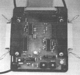
Construction
All the components except the LED's mount on a single sided PCB. The
component overlay is shown in figure 2 and track layout in figure 3.
The board is fairly tightly packed with many close tracks, so take due
care when constructing it. It may be worth checking your work with
a magnifying glass when you've finished.
 Before starting,
drill out the four mounting holes to 3mm (1/8"). There are a large
number of wire links, and these should be fitted first since many of them
pass underneath other components. Thin tinned copper wire (about
28 SWG) is ideal. With thicker wire it may be more difficult to
avoid short circuits unless it is sleeved.
Before starting,
drill out the four mounting holes to 3mm (1/8"). There are a large
number of wire links, and these should be fitted first since many of them
pass underneath other components. Thin tinned copper wire (about
28 SWG) is ideal. With thicker wire it may be more difficult to
avoid short circuits unless it is sleeved.
The remaining components may now be fitted, in any convenient order.
Sockets may be used for the IC's if desired, although LS TTL is unlikely
to be damaged by soldering. On the prototype, the LED's (D5 and
D6) were mounted on the case. If you wish to do the same, fit terminal
pins in their positions on the board.
SK1 and SK2 should be fitted facing towards the edge of the PCB.
When fitting SK3, be sure to get the 'V' indicator which marks pin 1 in
the position shown. If in doubt, the large polarising gap goes towards
the centre of the PCB.
You now need to establish whether your printer has a 5V output on pin
18 of the centronics connector. If you have the manual, check the
section towards the back that gives the interface connections. Otherwise
you will have to get your test meter out!
If you have a 5V output, link pads SK4 to SK5, and omit C8, IC8 and SK6.
If you don't have a 5V output fit the above components and omit the link.
Terminal pins should be fitted for SK6. IC8 will not need a heatsink
if the unregulated supply is below about 10V, otherwise you will need
to fit one and you may have to find a rigid method of mounting the pair.
Ribbon Cable
The PCB is connected to the printer with a piece of 40 way ribbon
cable, no more than about 1 metre long. Fit the 40 way IDC socket
to one end of the cable. The red stripe on the cable indicates pin
1, and should go to the 'V' mark on the connector. Position the
cable so it emerges on the side of the connector with the polarising bump.
The strain relief clip should now be fitted which reverses the cable direction.
Now separate wires 37 through 40 - these are the four farthest from the
red wire. Cut these four off close to the 40 way IDC socket.
Now fit the 36 way Centronics plug to the other end of the cable, again
with the red wire towards pin 1.
Ribbon cable is best cut with a sharp pair of scissors. Try to cut
it square. You will probably need to trim both ends to avoid stray
strands causing short circuits. The connectors can be carefully
pressed together using a WorkMate or vice. If using a metal vice,
use couple of pieces of wood to protect the connector. Make sure
the connector is squeezed evenly and the cable is square.
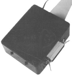
The Case
The PCB is specifically designed to fit an MB3 type plastic case.
The cutting and drilling details for the case and lid are shown in figures
4 through 7. All dimensions are in millimeters, although I have
given imperial alternatives for the hole sizes.
The lid drilling details are shown in figure 4. The PCB is fitted
to the lid with the tracks towards the lid. A single M3 nut gives
the correct spacing for the PCB, so that the connectors (SK1 and SK2)
just clear the lip at the edge. Once the board is in place, a second
nut on each screw holds it and the connectors firmly in place.
The two 6.5mm holes in one end of the case (fig 5) are for the LED's (D5
and D6). The 4mm hole in the other end (fig 6) is for the power
cable to the mains adaptor. If your printer has a 5V output you
won't need this hole. You may wish to fit a socket to match the
plug on your mains adaptor, in which case you may need to mount this lower
down to clear the PCB. My unit has a cable emerging from the 4mm
hole, which is connected to the mains adaptor by an in-line phono plug
and socket.
The rectangular cut-outs shown in fig 4 and fig 6 should be carefully
marked out with a steel rule, square and scriber. Drill a line of
small holes along the bottom edge (inside the line), then cut down both
sides with a junior hacksaw. You should now be able to break out
the unwanted section, and file the edges down to the lines. You
may need to remove part of the PCB mounting guides on the end of the case
where the ribbon cable enters.
The LED's (D5 and D6) are fitted in standard clips, and connected to the
board with thin wire. The anode of the LED goes to the pin closest
to the corner of the PCB in each case. If the LED wires are not
crossed over, the LED's will be nearest the socket they relate to.
If you are using an external power supply, this connects to SK6 with positive
closest to the corner of the PCB.
First Testing
If you are using an external power supply, check this out first.
Do not connect the unit to the printer or computers at this stage.
With the power supply connected and switched on, measure the voltage between
pins 1 and 2 of SK6 (the power input). This should be between 7.5V
and 10V. If the output voltage of your supply is switchable, find
a setting that gives a reading within these limits. If the voltage
is higher than 10V you will probably need a heatsink for the 7805 regulator
(IC8).
If the voltage is a little on the low side, this may be due to excessive
ripple on the output from your power supply. The cheaper plug-in
power supplies often have a low value smoothing capacitor, typically 470uF,
which causes significant ripple when the output is loaded.
If you have a digital multimeter you can measure the ripple by switching
the meter to AC volts. This meter will indicate an average value
for the ripple, which is about a third of the peak-to-peak value.
It is not too precise, but good enough for a rough check. If the
reading is over about 0.05V (0.15V pk-pk), connect a 1000uF or 2200uF
capacitor of appropriate voltage rating across SK6.
Set presets VR1 and VR2 fully anti-clockwise. Connect the unit
to your computers and printer, and switch everything on (printer first).
Watch the computer screens as they boot up, if any error messages appear
switch off immediately. Now check the voltage on the power pins
of one of the logic IC's, eg between pins 7 and 14 of IC6. The reading
should be 5V, +/- 0.25V.
Check the printer has some paper loaded and is switched on-line.
On one computer, type "COPY C:\CONFIG.SYS LPT1". It is easier to
stick to using DOS commands to generate simple print jobs for now, rather
than loading up applications. Your CONFIG.SYS file should be printed,
and the appropriate LED on the Printer Sharer should light and remain
on for about ten seconds after the C:\> DOS prompt reappears.
Try this from the other computer too.
Now try switching one computer off and printing from the other.
This should work OK too. You should be able to switch one computer
off and on while the other is driving the printer, without affecting the
printing. If your printer is Energy Star Compliant, switch both
computers off - the printer should enter standby mode as usual.
Final Testing
If you can reach
both keyboards at the same time (or borrow an assistant), try setting
both print jobs off at the same time by hitting both Enter keys simultaneously.
One computer will inevitably get the printer first, and the other will
have to wait. Both files should be printed correctly, and neither
computer should give an error message. There should be a delay of
about ten seconds after the first printout finishes. The LED's on
the Printer Sharer show the state of progress.
The only job remaining is to set up the timeout delay. In many cases
the ten seconds obtained with both presetss fully anti-clockwise will
be fine, however if you have a slow computer or a slow application you
may need to extend the delay to prevent the other computer getting in
partway through a print job.
On the slower computer, load up the application that prints the slowest
and start a large print job. If you use Windows, you could try printing
in the background while carrying out some disk intensive activity such
as loading another application or sorting a large database.
Watch the appropriate LED on the Printer Sharer. If it goes off
during the print job, increase the delay for that printer by turning the
appropriate preset gradually clockwise until the LED remains on.
Once you have found the correct setting, turn it up a fraction more (just
to be sure). You can either set the other preset to the same position,
or carry out the same test on the other computer.
In Use
There isn't much to it really - fit it and forget it! You won't
need to see the LED's in normal use, so the unit can be hidden on the
floor behind a desk or wherever.
The Printer Sharer should give years of reliable service, and make your
live that little bit easier! Now all we need is some method of changing
the paper automatically...
Parts List
Resistors (all 0.25W 5%
or better)
R1,R2,R3,R4,R5,R6,R7,R8,
R9,R10,R11,R12,R13,R14,
R15,R16,R17,R18,R19,R22,
R29,R30,R31,R32,R33,R34,
R35,R36,R37
4K7
(29 off)
R20,R21,R27,R28
470R
(4 off)
R23,R24
220K
(2 off)
R25,R26
22K
(2 off)
VR1,VR2
1M0 Horizontal Preset (2 off)
Capacitors
C1
47uF 16V Radial Elect
C2,C3
100p 0.2" pitch (2 off)
C4,C5
100u 16V Radial Elect (2 off)
C6,C7
470p 0.2" pitch (2 off)
C8*,C9*
100n 0.2" pitch (2 off)
Semiconductors
IC1,IC2
74LS541 8-bit tri-state buffer (2 off)
IC3
74LS244 Dual 4-bit tri-state buffer
IC4,IC5
7407 Hex open-collector buffer (2 off)
IC6
74LS32 Quad OR gate
IC7
74LS123 Dual retriggerable monostable
IC8*
7805 5V positive voltage regulator
TR1,TR2
BC548 NPN transistor
(2 off)
TR3
BC558 PNP transistor
D1,D2,D3,D4,D7,D8,D9,D10 1N4148 Signal Diode
(8 off)
D5,D6
RED 5mm LED
(2 off)
Miscellaneous
SK1,SK2
36 way R/A PCB Centronics socket (2 off)
SK3
40 way IDC box header
40 way IDC ribbon cable socket, 40 way ribbon cable (1 metre), 36 way
IDC centronics plug, DC PSU (7.5V to 10V @150mA, unregulated)*, socket
to suit plug on PSU*, Box type MB3, PCB, LED clips for D5 & D6 (2
off), M3 x 20mm countersunk screws (4 off), M3 nuts (8 off), 28 SWG tinned
copper wire, thin two core figure 8 wire.
Note
- components marked * are only required for external power supply arrangement.